How to Avoid Getting Totally Skewed – Part 1
The first of a three-part series on designing around glass-weave skew.
Au: This column is a comprehensive follow-on to our June column. With some overlap, these may be read together or independently.
In June I discussed the differences between 1067 and 106 glass styles, introducing the concept of “glass-weave skew” or the “fiber-weave effect.” Here in part one of a series on glass-weave skew, I’ll introduce its causes and when or why a hardware designer might care. In part two, we will discuss mitigation techniques and cost, and in part three we’ll do a deeper dive on the impact of glass styles on precipitating or mitigating skew.
First, a memory. While writing this, I kept thinking of my first time on the German Autobahn, in the late 1990s. We were coming back from a HyperLynx SI workshop and – as weird as it sounds even 20 years later – my driver was going just under 240kph (~150mph). As the semi-naive American in the car, I thought I should offer some chitchat on the four-hour drive to Munich to keep the driver awake. In an almost robotic tone, my German counterpart said, “I cannot talk at this speed.” I don’t suppose I’ll ever forget that comment.
I also noticed Autobahn drivers were generally better about using the correct passing lanes and signaling.
If you’re driving fast enough, there’s zero room for error, and you need to think proactively to survive.
For context, boards on the sending and receiving end of 99.9% of the world’s data transmission rely on copper traces or wires that use differential signaling to move data from A to B and B to A. Without differential signaling, the Internet, along with all the computers and cellphones we rely on, would not be possible, and your children would be looking to you rather than the Internet for advice and affirmation.
Differential skew
Today’s ICs send data over differential pairs in PCBs at rates as high as 32 to 56Gb/s. At these speeds, very small variations in the laminates used to fabricate PCBs can destroy a data path, if care is not taken in how these paths are designed and manufactured. A primary variation that can significantly compromise these interconnects is skew in a data path.
Glass-weave skew (GWS), alternately known as the fiber-weave effect (FWE), has become a hot topic in high-speed digital design over the past 10 years. The phenomenon is precipitated by the following ingredients:
- The need for near-complete symmetry between two halves of a differential pair.
- Progressively increasing bit rates.
- An inhomogeneous cross-sectional environment around each half of the differential pair for glass-fabric-based laminates.
Fortunately, it’s not quite as complicated as it sounds once you break the problem into parts and then consider the potential solutions.
Primary sources
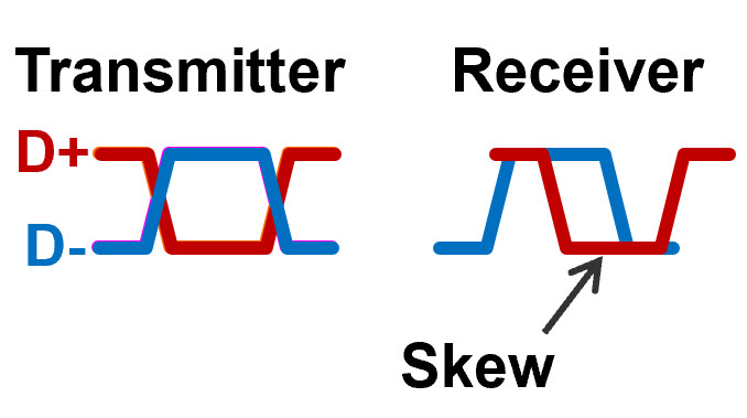
Primary sources. Misalignment between the two differential signals, illustrated as “skew” in FIGURE 1, can result in eye closure and inter-symbol interference (ISI) – system-crippling communication problems in differential signaling. When the two signals of a differential pair arrive at the receiver at different times, the receiver can misinterpret what data bits are sent.
As an example, think of a cellular call or an online meeting where you or someone on the other end are “dropping bits.” The audio gets choppy. The same phenomenon is experienced by receivers when ISI is present. If the resulting error rate in hardware you’ve designed exceeds the ability of the data path to correct for errors, the link fails, which can cause your boss to wonder why they hired you.
Skew or misalignment of the two edges in a differential pair can come from three places:
- Signal misalignment coming out of the transmitter due to length mismatches in the IC packages
- Different PCB routing lengths
- Differences in flight time on the two paths due to GWS.
Relative to the skew sources noted above, most ICs today maintain alignment at the package level, though package skew and crosstalk are important issues to watch. And modern PCB layout tools can match lengths fairly well, depending on routing density, BGA pitch and complexity. Once these first two sources are accounted for, that leaves “glass-weave skew,” the subject of this column, our primary area of concern.
What’s the fiber-weave effect?
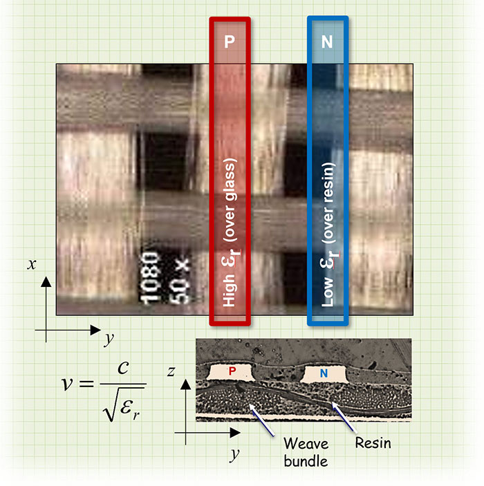
Simply stated, the greatest source of local dielectric constant variation between the two lines that make up a differential pair is more glass under one line than the other.
Electrical-grade glass fabric has a Dk (εr) approaching 7.0, while most resins have Dks approaching 3.0. Combine the two in cores and prepregs, and the effective Dk of the material, i.e., the values reported by laminate manufacturers as a function of resin content (%) and frequency, ends up around 4.0. Chances are good, however, one of the differential signals will “see” more resin than the other half, so the result is two different effective Dks and, by extension, two different average propagation velocities. A signal’s propagation velocity is inversely proportional to the square root of the effective, average Dk of the medium surrounding each half of the differential pair (FIGURE 2). The speed of the signal with more glass around it (εr approaching 7.0) will be slower than the one with more resin. The resulting difference in total delay is referred to as glass-weave skew.
If one line in a differential pair sees a higher or lower effective Dk than the other, there will be skew in the propagation delay between the two lines. This will result in mode conversion, and in some cases can completely close the eye at the receiver.
Defining skew
Differential skew, or simply “skew,” is typically measured in picoseconds (ps). In FIGURE 3, the two waveforms are perfectly aligned and cross exactly in the middle. But if one signal arrives before the other, the resulting skew distorts the eye and often results in data errors.
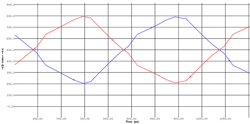
FIGURE 4 shows the same differential pair as Figure 3 with 40ps of skew. This isn’t at all an exaggeration. Chances are good your last design had the potential for twice this level of differential skew, though you wouldn’t know it until field failures were tied to the semi-random alignment of the differential signals and underlying
glass structure.
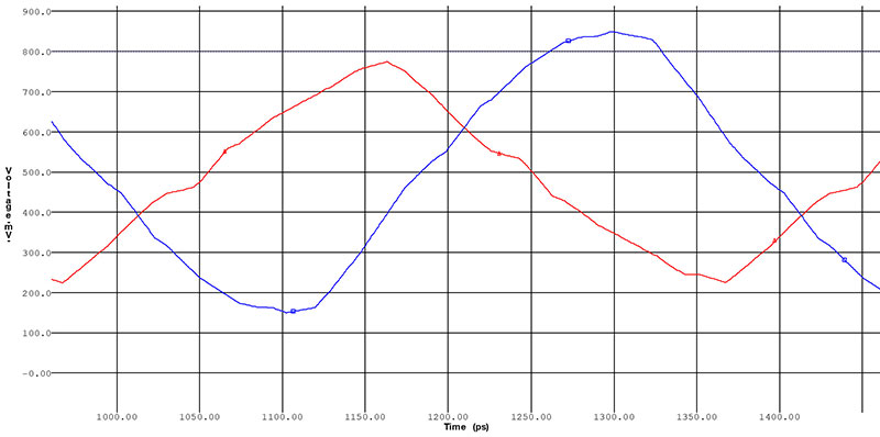
Prototypes are different from production boards 100% of the time due to glass-weave skew.
Differential-skew tolerance
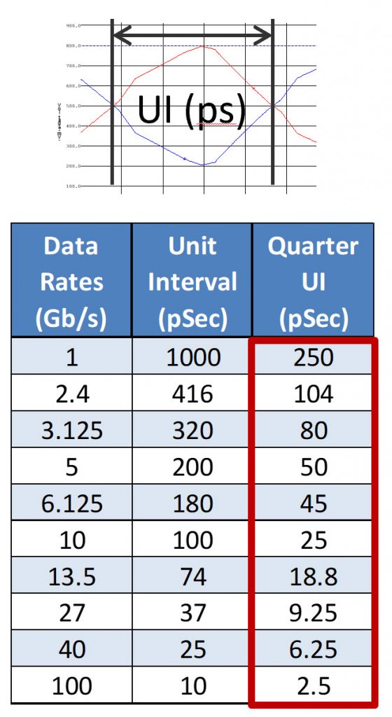
How much glass-weave skew is too much? Each differential serial-channel standard and speed has its own tolerance for skew. Most standards or chip manufacturers offer guidance on skew tolerance, but we can generically characterize that a channel’s tolerance for skew is described as roughly 25% of the bit stream’s unit interval (UI). For example, a 1Gbps (500MHz) signal would have a UI of 1000ps. Using 25% as a guideline, that represents a 250ps skew tolerance. That’s a wide window, and that’s why most engineers didn’t need to worry about GWS 20 or more years ago.
Fast forward to designing at 10Gbps (5GHz). The unit interval will be 100ps, and the skew tolerance will decrease proportionally to around 25ps. PCI Express 4.0’s signaling speed, at twice the speed of PCIe-3.0, is even faster at 16Gbps (8GHz). This maps to roughly a 60ps UI and 15ps of skew tolerance – half of the 30ps skew tolerance in PCIe-3.0.
If you aren’t dealing with GWS on your current designs, it’s likely you will be on the next one, so you might as well saddle up.
Predicting GWS
Typical skew values across a differential channel range from 10 to 100ps, but predicting GWS is tricky. What is the chance one line in a pair will see a different Dk than the other? There are systematic parameters like glass pitch, differential-trace pitch, glass weave style, line length, and fabric and resin Dk (εr). But the actual GWS for a particular differential pair also heavily depends on the chance alignment of the glass bundles under the two lines. Because there’s a hard-to-predict, semi-random component, 95% of your boards may work fine, while the remaining boards are dropping bits.
With glass-weave skew, prevention is much more realistic than prediction.
Preventing GWS
While GWS is a real problem, it’s equally hard to characterize because it is statistical in nature. What is the chance one line in a pair will see a different dielectric constant than the other? It depends on the pitch of the lines, length of the lines, laminate composition, and the relative chance alignment of the glass bundles under the two lines.
A simple, cost-free panacea for GWS would be nice, but almost all remedies represent partial solutions that may work at some frequencies and line lengths but not others. I’ll provide an overview of the cornucopia of design remedies to mitigate GWS in part two of this series.
TABLE 1. Data Rates, Unit Intervals and Approximate Tolerances for Skew1
Reference
1. Lee Ritchey, “Minimizing Skew in High Speed Differential Links,” 2015.