Who Should Be Concerned about the Fiber-Weave Effect?
Most boards will work just fine. But what if they don’t?
Over the past year, I’ve written a good bit about glass-weave skew (GWS) and next-generation loss requirements, using PCI Express guidelines as a means of tracking what higher frequencies do to eye patterns. This month, we’ll combine important elements of both these technology series, with just a bit of review in order to make this column one that can be read as-is.
The problem with human behavior is many of us wait for some sort of catastrophic event before we course-correct. When should we get serious about glass-weave skew, as opposed to ignoring it, while hoping it doesn’t turn around and bite us at some point in the field? (A near-worst-case scenario.)
When I was marketing signal-integrity software in the 1990s, many engineers would appear on my radar reactively, playing whack-a-mole after spinning multiple prototypes or field failures. Over time, the list of possible causes grew to include crosstalk, loss in all its forms, and eventually power integrity. I’ve noticed many of today’s hardware teams are sort of on cruise control relative to the “fiber-weave effect” as a design concern, so my objective here is to explore the concept of whether designers should worry about it proactively, given the potential impact of seemingly random field failure in production.
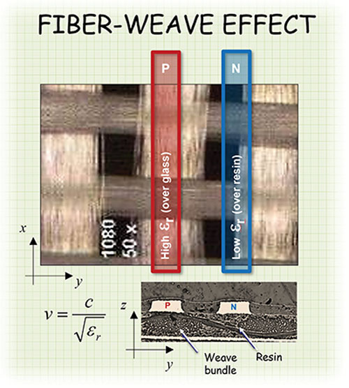
Background. Practically speaking, glass-weave skew and the fiber-weave effect (FWE) are the same thing. Or, more accurately stated, the fiber-weave effect causes glass-weave skew. Semantics aside, the fiber-weave effect is caused by one signal in a differential pair seeing a different micro-environment than the other signal in the pair. This is caused by the fact that “E” glass has a Dk of around 6.8, and resin has a Dk of around 3.0, though it varies from one resin system to the next. FIGURE 1 shows if one signal is primarily adjacent to glass (P) in the resin-epoxy dielectric mixture, and the other differential signal is running across a mixture of glass and resin (N), the effective Dk is going to be different for the two signals, resulting in impedance and propagation-velocity variation as well.
Lee Ritchey provides TDR results showing these effects, while contrasting two different glass styles: 1080 and 3313 mechanically spread glass (FIGURE 2). Notice how much more uniform the impedance is as it travels across the glass weave when signals run parallel to both the weave (navy blue) and the fill directions (purple and green plots) compared to 1080 glass. This results in very low skew. Weaves known to cause skew in differential pairs include 106, 1080, 2116, and 7628 glass.
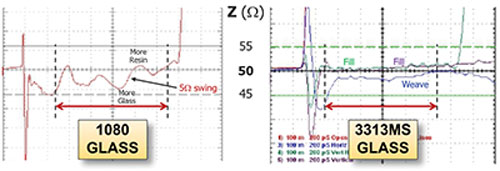
The 1080 glass exhibits a 5Ω swing. With the 3313MS glass, impedance variation is much less significant, with the variation parallel to the weave direction more significant than the signal running parallel to the fill.
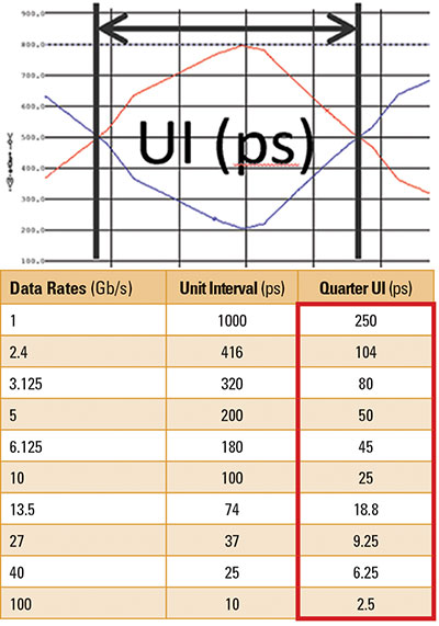
Each differential serial-channel standard and speed has its own tolerance for skew. Most standards or chip manufacturers offer guidance on skew tolerance, but we can generically characterize that a channel’s tolerance for skew is described as roughly 25% of the bit stream’s unit interval (UI). For example, a 1Gbps (500MHz) signal would have a UI of 1000ps. Using 25% as a guideline, that represents a 250ps skew tolerance. That’s a pretty wide window, and why most engineers didn’t need to worry about GWS 20 years ago. Fast forward to designing at 10Gbps (5GHz). The unit interval will be 100ps, and the skew tolerance will decrease proportionally, to around 25ps.
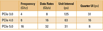
PCIe example. We could talk about any number of bus standards, but I prefer to use PCI Express, since it’s one many of us are familiar with. Doing the same math as above, TABLE 2 shows that as you progress from PCIe 3.0 to PCIe 4.0 and PCIe 5.0, the tolerance for skew from all sources goes from 31ps, which is tight to begin with, down to 8ps. At any of these bus speeds, hardware designers can no longer ignore the prospect of glass-weave skew sneaking in and semi-randomly compromising otherwise well-planned designs!
Next, we’ll explore what actually happens to otherwise-pristine eye patterns.
Glass-Weave Skew’s Impact on Eyes
PCI Express 3.0. FIGURE 3 shows simulation results for an 8-Gbps signal using a material that was successful on platforms that used PCIe 3.0. The blue keep-out region doesn’t have any bits encroaching on it, which is what we want. This is simply intended as a high-level example of the interplay between frequency, eye mask, eye diagram and skew.
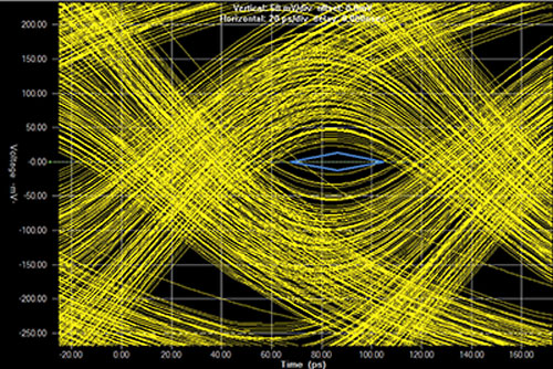
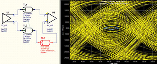
According to Table 2, if we introduce 45ps of fiber-weave-effect-induced skew into this differential signal – one that was already near the edge, as shown in Figure 3 – the eye pattern should be compromised. FIGURE 4 shows this is indeed the case. The 25% unit interval rule-of-thumb seems to hold true here. The actual amount of glass-weave skew can be significantly more, depending on the interconnect length and the semi-random alignment between the two lines in a differential pair compared to the underlying glass fabric.
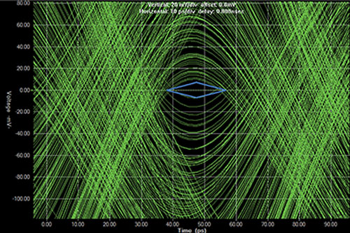
PCI Express 4.0. Keeping with this theme, let’s consider a more expensive, lower-loss material for the next-generation requirement. We’ll use 16Gbps and the PCIe 4.0 eye mask. FIGURE 5 shows the result. Note the vertical scale was changed, adapting to the tighter keep-out requirements for PCIe 4.0 compared with 3.0.
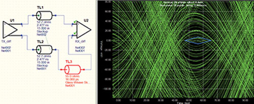
Using guidance from Table 2, if we introduce just 16ps of fiber-weave-effect-induced skew into this differential signal – one that was already near the edge, as shown in Figure 5 – the eye pattern should be compromised, as FIGURE 6 shows. The same amount of skew that was perfectly acceptable for PCIe-3.0, 16ps, was absolutely unacceptable for PCIe-4.0.
PCI Express 5.0. The same simulation exercise could be performed for PCIe 5.0 and higher frequencies, although the task of producing acceptable eye patterns at the receiver gets much tougher and of course the tolerance for skew decreases, as expected.
Parting thoughts. One of the problems with the fiber-weave effect is prototypes may work just fine. And 95% of the signals on 95% of the boards may work just fine. Systematic elements tied to glass-weave skew result from most trace routing running parallel to the weave and fill directions in the adjacent glass weave. And there’s a systematic element tied to frequency effects, design margins and the pitch of the differential pairs as they relate to the adjacent glass. More of these effects are controllable than hardware designers realize, in my observation.
And mitigating the risk begins with the realization that this may be something you need to be concerned about as speeds increase. The frequency guidelines offered here hopefully answer the question I posed at the top.
For glass-weave skew mitigation tips, I covered the means by which glass-weave skewed can be controlled in a previous series in PCD&F. Part 2 surveyed the options, and parts 3 and 4 drilled into more detail, including glass styles and differential pitch. See pcdandf.com for more details.
References
1. Lee Ritchey, Speeding Edge, “Minimizing Skew in High Speed Differential Links,” December 2015.